Quartz Design Guide
Martin Welford
This page includes essential information for anyone designing a base-board for Quartz. Please read everything carefully and ask if there are any details you are not sure about.
Pin Multiplexing
The Vybrid SoC includes many functions which are multiplexed on to a small number of pins. The first part of a design is to figure out what features you need and which pins will supply these features. There are two tools which can help:
- This Freescale spreadsheet includes a comprehensive list of every pin and the alternative functions.
- Use the Altium schematic Symbol. This includes the most common alternate functions as part of the symbol.
Reference Designs
Reference designs are the best place to start when looking at implementing a particular features. The Quartz Development Kit should be copied as much as possible as this will ensure you not only have a working hardware circuit, but the OS drivers will also need little or no modifications.
Boot Settings
Vybrid is capable of booting from a wide range of sources, however we have limited this to:
- NAND flash
- SD Card
- USB (for programming)
The CN version of Quartz includes circuitry to setup boot pins during reset, and has no effect on these pins when the board comes out of reset.
If you need to boot from another source (e.g. QSPI), contact us and we can determine the best way to achieve this.
Quartz includes 3 signals which specify the boot source. This table shows the settings required for boot:
| Boot Source | BOOT_MODE0 | BOOT_MODE1 | BOOT_NAND |
|---|---|---|---|
| USB* | 0 | 0 | 0 |
| SD Card | 1 | 1 | 0 |
| NAND | 0 | 1 | 1 |
*If the Vybrid on-chip fuses have been blown, ensure there is no bootable SD card present when attempting to boot to the USB loader mode.
LGA Boot Settings
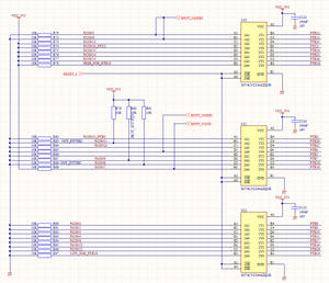
The LGA version lacks the boot logic present on the CN in order to save space. This should be added to your base-board, or you can blow the internal Vybrid fuses. We recommend you start out with this logic on your first prototypes. Click the image blow for a larger view.

Essential Features for your Base-Board
There are several features that will greatly assist debugging. If you are unable to add these for space or cost reasons, we strongly recommend you create a daughter board and add a connector so you have access to these features:
| Serial Port | Include a dedicated port for debug purposes |
|---|---|
| Ethernet | Ethernet is a great way to connect to a device for debugging or downloading large OS images and files. |
| USB Function | The USB Function port is an easy way to program the on-board NAND flash. |
| Status LED | Status LEDs are always useful to have when debugging low level code. |
Dual Ethernet on the LGA version
The CN module has two Ethernet PHYs fitted compared with a single PHY on the LGA version. The LGA PHY is attached to FEC 1 on the Vybrid. The FEC 0 signals are accessible on the Quartz interface so it is possible to add a second PHY on your base-board. Quartz uses KSZ8051RNL PHYs and we recommend you use the same part for software compatibility if adding a second PHY to your LGA design.
Ethernet MAC Addresses
Quartz modules do not include a MAC address.
We can supply a small number from our block for prototypes, however you will need to purchase addresses for production quantities. These can be purchased through IEEE.
There are two options for doing so:
1. IAB which gives you 4096 addresses: http://standards.ieee.org/develop/regauth/iab/
2. OUI if you need more: http://standards.ieee.org/develop/regauth/oui/index.html
Remember that you will need TWO MAC addresses per board if you use the dual Ethernet feature.
On this page: