ODK-6 Connector Summary
- Martin Welford
Owned by Martin Welford
Last updated: Aug 15, 2016
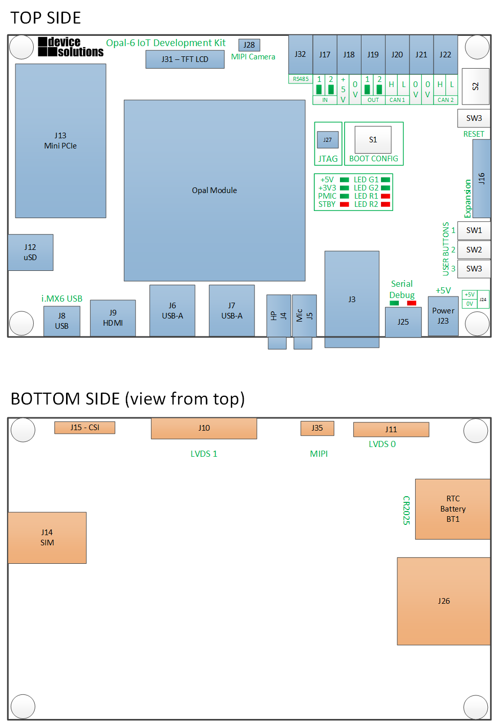
This table details the connectors on the Opal-6 Development Kit and where they can be found. The information relates to the latest revision of the board.
| Designator | Description | Location |
|---|---|---|
| J1,J2 | Interface connectors for the Opal-6 CPU Module | Top |
| J3 | RJ-45 Ethernet connector | Top |
| J4 | Headphone stereo audio out | Top |
| J5 | Microphone input | Top |
| J6, J7 | USB Host x 4 | Top |
| J8 | USB mini-B - USB Function on i.MX6 | Top |
| J9 | HDMI | Top |
| J10 | 30-way connector for LVDS 1 | Bottom |
| J11 | 40-way header for LVDS 0 | Bottom |
| J12 | uSD card | Top |
| J13 | Mini PCIe connector | Top |
| J14 | SIM card for Telit module | Bottom |
| J15 | 30-way connector for CSI0 - parallel Camera interface | Bottom |
| J16 | 40-way expansion connector with MIPI-DSI, UART, ECSPI, PCIe and GPIO | Top |
| J17 | Push-wire connector - 2x 5V inputs | Top |
| J18 | Push-wire connector - 2x 0V | Top |
| J19 | Push-wire connector - 2x 5V outputs | Top |
| J20 | Push-wire connector - CAN1 | Top |
| J21 | Push-wire connector - 2x 0V | Top |
| J22 | Push-wire connector - CAN2 | Top |
| J23 | Barrel connector for main power in (6-24V) | Top |
| J24 | 0.1" header for main power in (5V) | Top |
| J25 | USB mini-B for Serial Debug | Top |
| J26 | SD Card (SD2) | Bottom |
| J27 | JTAG (10-pin connector) | Top |
| J28 | MIPI Camera connector for LI-OV5640-MIPI-AF | Top |
| J29, J30, J34 | Test headers (not fitted) | Top |
| J31 | 40-way expansion header - Parallel display (DISP0) and SATA (with D/Q module) | Top |
| J32 | Push-wire connector - RS485 | Top |
| J35 | MIPI expansion with full CSI + MIPI Display | Bottom |
| S1 | 8-way DIP switch for boot configuration | Top |
| S2 | 8-way DIP switch for CAN termination | Top |
| SW1, SW2, SW3 | Push button switches for user application | Top |
| SW4 | Push button for RESET | Top |
| BT1 | Battery connector for backup coin-cell | Bottom |
Previous Revisions
, multiple selections available,