ODK-6 Connector Summary - Rev B
- Martin Welford
Owned by Martin Welford
Last updated: Jul 26, 2016
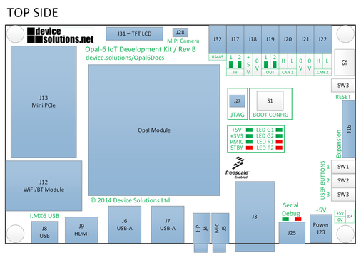
This table details the connectors on the Opal-6 Development Kit and where they can be found. The information relates to revision B.
| Designator | Description | Location |
|---|---|---|
| J1,J2 | Interface connectors for the Opal-6 CPU Module | Top |
| J3 | RJ-45 Ethernet connector | Top |
| J4 | Headphone stereo audio out | Top |
| J5 | Microphone input | Top |
| J6, J7 | USB Host. The top port on J7 is also connected to the Mini PCIe connector. To use it J7 you must remove R122 and R123 which are located on the bottom layer next to J7. | Top |
| J8 | USB mini-B - USB Function on i.MX6 | Top |
| J9 | HDMI | Top |
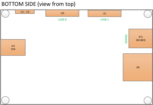
| J10 | 30-way connector for LVDS 0 | Bottom |
| J11 | 30-way connector for LVDS 1 | Bottom |
| J12 | Laird WiFi/BT module connector | Top |
| J13 | Mini PCIe connector | Top |
| J14 | SIM card for Telit module | Bottom |
| J15 | 30-way connector for CSI0 - parallel Camera interface | Bottom |
| J16 | 40-way expansion connector with MIPI-DSI, UART, ECSPI, PCIe and GPIO | Top |
| J17 | Push-wire connector - 2x 5V inputs | Top |
| J18 | Push-wire connector - 2x 0V | Top |
| J19 | Push-wire connector - 2x 5V outputs | Top |
| J20 | Push-wire connector - CAN1 | Top |
| J21 | Push-wire connector - 2x 0V | Top |
| J22 | Push-wire connector - CAN2 | Top |
| J23 | Barrel connector for main power in (5V) | Top |
| J24 | 0.1" header for main power in (not fitted) | Top |
| J25 | USB mini-B for Serial Debug | Top |
| J26 | SD Card (SD2) | Bottom |
| J27 | JTAG (10-pin connector) | Top |
| J28 | MIPI Camera connector for LI-OV5640-MIPI-AF | Top |
| J29, J30 | Test headers (not fitted) | Top |
| J31 | 40-way expansion header - Parallel display (DISP0) and SATA (with D/Q module) | Top |
| J32 | Push-wire connector - RS485 | Top |
| S1 | 8-way DIP switch for boot configuration | Top |
| S2 | 8-way DIP switch for CAN termination | Top |
| SW1, SW2, SW3 | Push button switches for user application | Top |
| SW4 | Push button for RESET | Top |
| BT1 | Battery connector for backup coin-cell | Bottom |
, multiple selections available,