ODK-6 System Components
- Martin Welford
This page details each of the features on the Opal-6 IoT Dev Kit. These are categorised as:
Opal-6 SoM
The Opal-6 System on Module (SoM) is at the core of the ODK.
The Dual Lite version is included as standard with the ODK.
User Interface Components
Display Interfaces
HDMI
Opal-6 includes a standard HDMI interface allowing connection to monitors, TVs and other HDMI equipped interfaces. It supports displays with a resolution of up to 1920x1080.
LVDS
The Opal-6 Development Kit has 2 LVDS connectors:
- J10 - Freescale 10.1" panel connector
- J11 - Expansion header
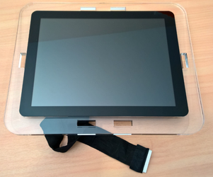
The Freescale 10.1" LVDS-1 panel (sometimes known as the Hannstar panel) is shown below. This display includes a capacitive touch interface and can be purchased from NXP or a distributor via this link. THe part number is MCIMX-LVDS1.
A 0.05" pitch expansion header has been used for the i.MX6 LVDS0 interface. It includes the LVDS signals, I2C interface for a touch controller and various GPIO signals.
| Signal | Pin | Pin | Signal |
|---|---|---|---|
| +5V | 1 | 2 | +5V |
| +5V | 3 | 4 | +5V |
| +3.3V | 5 | 6 | I2C_SCL |
| +3.3V | 7 | 8 | I2C_SDA |
| 0V | 9 | 10 | 0V |
| LVDS0_TX2_N | 11 | 12 | GPIO_ENABLE |
| LVDS0_TX2_P | 13 | 14 | GPIO_INTERRUPT |
| 0V | 15 | 16 | GPIO_BACKLIGHT_EN |
| LVDS0_TX1_N | 17 | 18 | CONTRAST |
| LVDS0_TX1_P | 19 | 20 | PWM2_OUT |
| 0V | 21 | 22 | 0V |
| LVDS0_TX0_N | 23 | 24 | NC* |
| LVDS0_TX0_P | 25 | 26 | NC |
| 0V | 27 | 28 | NC |
| LVDS0_CLK_N | 29 | 30 | NC |
| LVDS0_CLK_P | 31 | 32 | NC |
| 0V | 33 | 34 | NC |
| NC | 35 | 36 | NC |
| NC | 37 | 38 | NC |
| NC | 39 | 40 | NC |
NC = Not Connected.
Earlier versions of the development kit included two connectors for the Freescale panel.
Parallel TFT Expansion Connector
The ODK has an expansion connector which includes:
- +5V and +3.3V
- 24-bit parallel TFT signals from the i.MX6 DISP0 interface
- 4-wire resistive touch interface
- I2C
This connector does not work directly to a specific panel, but an interface board can be created for any display.
| Signal | Pin | Pin | Signal |
|---|---|---|---|
| +5V | 1 | 2 | +3.3V |
| DISP_DAT0 | 3 | 4 | DISP_DAT16 |
| DISP_DAT1 | 5 | 6 | DISP_DAT17 |
| DISP_DAT2 | 7 | 8 | DISP_DAT18 |
| DISP_DAT3 | 9 | 10 | DISP_DAT19 |
| DISP_DAT4 | 11 | 12 | DISP_DAT20 |
| DISP_DAT5 | 13 | 14 | DISP_DAT21 |
| DISP_DAT6 | 15 | 16 | DISP_DAT22 |
| DISP_DAT7 | 17 | 18 | DISP_DAT23 |
| 0V | 19 | 20 | 0V |
| DISP_DAT9 | 21 | 22 | DISP_DCLK |
| DISP_DAT9 | 23 | 24 | DISP_BUSY |
| DISP_DAT10 | 25 | 26 | DISP_ENABLE |
| DISP_DAT11 | 27 | 28 | DISP_HSYNC |
| DISP_DAT12 | 29 | 30 | DISP_VSYNC |
| DISP_DAT13 | 31 | 32 | 0V |
| DISP_DAT14 | 33 | 34 | TOUCH_XN |
| DISP_DAT15 | 35 | 36 | TOUCH_XP |
| I2C_SDA | 37 | 38 | TOUCH_YN |
| I2C_SCL | 39 | 40 | TOUCH_YP |
Audio
The ODK includes 2 x 3.5mm jack connectors for stereo audio out (green) and a microphone input (pink). This functionality is provided by a Freescale SGTL5000 audio codec.
MIPI Camera & Display
There are two interfaces for MIPI on the kit.
- Direct support for a Leopard Imaging LI-OV5640-MIPI-AF camera. This is based on the 5-megapixel OmniVision OV5640 image sensor module.
This is available from Arrow Electronics and Mouser Electronics. - Expansion connector with all MIPI camera lanes + MIPI display.
The expansion connector is a Molex 541670308 with the following pin configuration.
| Signal | Pin | Pin | Signal |
|---|---|---|---|
| CSI_DATA0_N | 1 | 2 | NC |
| CSI_DATA0_P | 3 | 4 | +5V |
| 0V | 5 | 6 | CSI_MIPI_SDA |
| CSI_DATA1_N | 7 | 8 | CSI_MIPI_SCL |
| CSI_DATA1_P | 9 | 10 | PWM2_OUT |
| 0V | 11 | 12 | CSI_PWON |
| CSI_DATA2_N | 13 | 14 | MIPI_GPIO |
| CSI_DATA2_P | 15 | 16 | DSI_DATA0_P |
| 0V | 17 | 18 | DSI_DATA0_N |
| CSI_DATA3_N | 19 | 20 | 0V |
| CSI_DATA3_P | 21 | 22 | DSI_DATA0_P |
| 0V | 23 | 24 | DSI_DATA0_P |
| CSI_CLKO_N | 25 | 26 | 0V |
| CSI_CLKO_P | 27 | 28 | DSI_DATA0_P |
| 0V | 29 | 30 | DSI_DATA0_P |
Buttons and LEDs
The ODK includes 3 push-buttons, 1 switch (this is switch 1 on the BOOT_CONFIG/SW1 switches) and 4 LEDs available for use in your application.
They use the following GPIO signals from the i.MX6:
| Button/LED | GPIO Pin |
|---|---|
| BUTTON1 | 3-31 |
| BUTTON2 | 3-30 |
| BUTTON3 | 4-13 |
| LED G1 | 3-05 |
| LED G2 | 3-01 |
| LED R1 | 3-04 |
| LED R2 | 3-14 |
| SWITCH_1 | 4-14 |
Connectivity
10/100/1000 Ethernet
The ODK has gigabit Ethernet. The LEDs on the connector indicate link status and network activity.
USB Host
The ODK has 4 USB host ports. These operate at 480Mbps and this functionality is provided by an SMSC USB chip IC.
The top port on J7 is also connected to the Mini PCIe connector. To use it J7 you must remove R122 and R123 which are located on the bottom layer next to J7.
USB Function
The USB mini-B port next to the main power input is connected to one of the OTG ports on the i.MX6 processor.
This is configured as USB function-only mode and operates at 480Mbps.
SD Card and uSD Card
The ODK includes both a standard SD card connector and, from revision D, a micro SD card connector. These can be used as a boot source or data storage.
FlexCAN
The ODK includes two FlexCAN channels. These have Freescale MC34901 transceivers and can be connected to via push-wire connectors.
Optional 60-ohm termination is provided by the switches on S2. Turn these switches ON to enable the termination.
PCIe Connector
The ODK includes a mini PCI express connector. This has a single PCI lane as well as USB and SIM card features.
SIM card interface
A SIM card connector is included to take standard large SIM cards. This is connected to the mPCIe socket for cellular modem use.
The ArrowONE Global SIM present on the Rev B kits is no longer supported.
Digital I/O Features
Digital Inputs
The Opal-6 Development Kit includes 2 digital inputs. These are protected from noise and spikes by a voltage divider, 5.6V zener diode and 100nF capacitor. Refer to the schematics for details in the input circuit. There are 2 LEDs on these ports to give a visual indication when the input is high.
| Input | GPIO Pin |
|---|---|
| INPUT 1 | 2-02 |
| INPUT 2 | 2-03 |
Digital Outputs
The 2 digital outputs on the ODK use p-Channel FETs with a +5V high-side configuration. Each output can supply up to 1A, but the total current will depend on the input power supply. There are LED indicators on each output showing when it is active.
| Output | GPIO Pin |
|---|---|
| OUTPUT 1 | 2-00 |
| OUTPUT 2 | 2-01 |
Debug Interfaces
USB Serial
The primary serial output from the Opal-6 module can be found on the Serial Debug USB mini-B connector located at the bottom right hand corner of the ODK. See the Getting Started section for information on setting up the required driver on your PC.
JTAG
A standard ARM 9-pin JTAG connector is located next to the configuration switches on the ODK.