ODK-6 Getting Started Guide
- Martin Welford
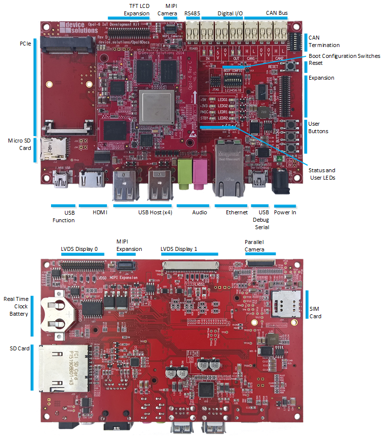
Getting to know the Development Kit
The images below show the location of the key features on the development kit.
Configuration Switches
Boot Setup
This table shows the switch setup required to boot from SD card, on-board eMMC or USB.
Switch 1 is not used for boot.
| Boot from: | 1 | 2 | 3 | 4 | 5 | 6 | 7 | 8 |
|---|---|---|---|---|---|---|---|---|
| eMMC | N/A | ON | ON | ON | ON | ON | ON | OFF |
| SD Card | N/A | OFF | ON | OFF | ON | OFF | ON | OFF |
| uSD Card | N/A | OFF | ON | OFF | OFF | OFF | ON | OFF |
| USB | N/A | X | X | X | X | X | OFF | ON |
Switch 1 is connected to GPIO 4-14 and is available for application use.
CAN Termination
The ODK includes 60-ohm termination resistors for each CAN channel. Turn ON switches 1 & 3 to terminate CAN1, and 5 & 7 to terminate CAN2.
| Switch | Terminates |
|---|---|
| 1 | CAN1_H |
| 3 | CAN1_L |
| 5 | CAN2_H |
| 7 | CAN2_L |
USB Host Ports
The top port on J7 is also connected to the Mini PCIe connector. To use it J7 you must remove R122 and R123 which are located on the bottom layer next to J7.
Power and Status LEDs
The power and status LEDs are located to the right of the Opal-6 module.
| LED | Color | Description |
|---|---|---|
| +5V | Green | Shows +5V is present on the main input |
| +3V3 | Green | Indicates the +3.3V power supply is operating correctly |
| PMIC | Green | Indicates the Opal-6 Power Management IC (PMIC) is operating. |
| STBY | Red | The PMIC is in standby mode and the board is not operating |
| LED G1 | Green | User programmable LED |
| LED G2 | Green | User programmable LED |
| LED R1 | Red | User programmable LED |
| LED R2 | Red | User programmable LED |
Powering up the board
The Opal Development Kit is supplied with a 5V/2A power pack. A supply capable of more than 2A may be required if you use several features at the same time - for example: Cell modem, LVDS displays with high-current backlights and the digital I/O.
Serial Debug and Configuration
The serial console on the ODK is on i.MX6 UART 4 and is accessible via USB. An FTDI FT230XS IC on the kit provides this interface.
Drivers are included in Windows 7 and 8 and available for other operating systems at http://www.ftdichip.com/Drivers/VCP.htm.
Software Application Development
Refer to the Getting Started Guide for your chosen Operating System.
Links will be added here when available.