ODK System Components
- Martin Welford
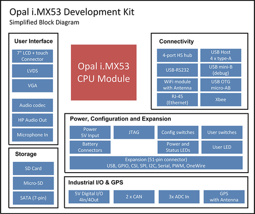
This page has details on each of the system components that make up the Opal i.MX53 Development Kit.
The block diagram below shows the main components on the Development Kit board, and how they are connected.
For details on specific i.MX53 features please refer to the Opal CPU Reference Manual.
Opal CPU Module
The Opal CPU Module is at the core of the Opal Development Kit. Opal includes a Freescale i.MX53 processor, 1GByte DDR3 RAM, up to 4GBytes of NAND flash, power management, and Ethernet PHY.
The Opal CPU module connects to the ODK via 2x 168-pin connectors. The connectors on the development kit are: Hirose FX10A-168P-SV1(71).
User Interface Components
The Opal i.MX53 CPU Module includes many display interface options. The ODK supports:
- Parallel LCD with specific support for a Datavision 7" TFT panel
- 2 x LVDS
- Analog VGA
The ODK is capable of driving two of these displays at the same time, provided the VGA output is less than 1920 x 1080. Please refer to the documentation for your Operating System for details on the display combinations that are supported.
7" LCD and Touch-Screen
The ODK provides dedicated connectors for an 18-bit 800x480 Datavision DTFS070A5SHLA-D02 7" LCD with resistive touch-screen. The connectors (J7 for the main LCD connection and J9 for the touch-screen connection) are located on the back of the board. This connection uses the DISP0 parallel interface from the i.MX53 and the touch-screen controller from the DA9053 PMIC on the Opal module.
Contact Device Solutions to obtain one of these screens.
VGA
The VGA connector on the ODK interfaces directly with standard monitors and can output a maximum resolution of 1920x1080.
LVDS
The ODK has two LVDS connectors which are identical to the LVDS connector on the Freescale Quick Start Board (QSB). These support the Freescale LVDS-1 display with capacitive touch.
Touch on both displays is not currently supported in software.
Audio
A Freescale SGTL5000 audio codec is included on the ODK. 3.5mm Stereo headphone and microphone connectors are provided.
Communications Components
USB Host
The ODK includes 4 high-speed (480Mbps) USB ports. This is implemented using a 4-port hub and the USB Host port on the i.MX53. Two of the ports are also available on the expansion connector.
USB Function
The ODK implements the i.MX53 USB OTG port as a USB function for connections to a PC.
Note that this port is technically an OTG port (allowing for host as well as device connections), however it is not connected as such on the ODK.
Serial Ports
The Opal CPU module includes 5 serial ports. These are connected to the following components on the Opal Development Kit:
Serial Port | Opal Development Kit Use |
|---|---|
UART 1 | XBee Socket and Expansion Connector |
UART 2 | Used for Bluetooth on the Wi-Fi/BT module (Rev D and above) |
UART 3 | Expansion Connector |
UART 4 | Debug port via USB-to-serial IC. Refer to section for 2.5 details. |
UART 5 | GPS |
Ethernet
The ODK provides 10/100 Ethernet via a RJ-45 connector.
The majority of the Ethernet functionality is implemented on the Opal CPU module (the MAC as part of the i.MX53 + an external PHY). The only additional components on the Development Kit are a few resistors and capacitors, and a RJ-45 connector with integrated magnetics. The RJ-45 connector includes the 2 status LEDs that indicate:
- Orange: Link Status
- Green: Network Activity
Wi-Fi & Bluetooth
The Wi-Fi interface on the ODK is provided by a connector for a Summit Data MSD40NBT module. An external antenna is required for this module.
Note that this is available on revision D boards and above.
Function | Port/GPIO |
|---|---|
WiFi |
|
Data | eSDHC2 |
WIFI_RESET | GPIO2-27 |
WIFI_CHIP_PWD | GPIO5-00 |
Bluetooth |
|
Data | UART2 |
BT_HOST_WAKE | GPIO3-24 |
BT_RESET | GPIO3-22 |
XBee Socket
The ODK includes a standard XBee socket allowing easy connection of a variety of OEM RF modules.
Pin 13 (ON/SLEEP) is connected to an LED on the development board. The nc pins are not connected on the development board.
Function | Pin | Pin | Function |
|---|---|---|---|
3.3V | 1 | 20 | nc |
UART1_RXD | 2 | 19 | nc |
UART1_TXD | 3 | 18 | nc |
nc | 4 | 17 | nc |
nc | 5 | 16 | UART1_RTS |
nc | 6 | 15 | nc |
nc | 7 | 14 | nc |
nc | 8 | 13 | ON/SLEEP |
nc | 9 | 12 | UART1_CTS |
0V | 10 | 11 | nc |
Power, Configuration and Expansion
Power Connections
The Opal Development Kit is powered with 5V from either a barrel connector (2.5mm centre positive pin) or 2-pin header.
A 2A power supply is recommended, especially if you have an LCD connected.
Power and Status LEDs
The ODK includes 4 LEDs to indicate status. Details can be found in section 2.2.
Configuration Switches
The ODK includes 8 configuration switches which control the boot process. These are detailed in the earlier Getting Started section.
User Buttons and LEDs
2 LEDs and 2 buttons are included on the ODK for use in applications.
These are connected to the following GPIO pins on the i.MX53:
Button/LED | i.MX53 GPIO |
|---|---|
BUTTON 1 | GPIO4-03 |
BUTTON 2 | GPIO4-02 |
LED 1 (Red) | GPIO1-02 |
LED 2 (Green) | GPIO1-04 |
JTAG Connector
A standard 20-pin ARM JTAG connector is present to allow firmware and application debugging using appropriate tools.
Accelerometer
The Opal Development Kit includes a Freescale MMA8450QT accelerometer.
The MMA8450QT features include:
- ±2g/±4g/±8g dynamically selectable full-scale
- 12-bit digital output
- I²C digital output interface (operates up to 400 kHz fast mode)
- Programmable two interrupt pins for eight interrupt sources
- Embedded four channels of motion detection
- Free-fall or motion detection: two channels
- Pulse detection: one channel
- Transient detection: one channel
- Orientation (portrait/landscape) detection with hysteresis compensation
- Automatic ODR change for auto-wake and return-to-sleep
Consult the Freescale web site for more information on this part.
The accelerometer is connected to the
Function | Connected to: |
|---|---|
I2C interface | I2C1 |
Enable pin | GPIO5-22 |
Interrupt 1 | GPIO5-19 |
Interrupt 2 | GPIO5-18 |
Expansion Connector
The ODK includes a 51-pin expansion connector with:
- Power
- I2C
- Camera Input
- One-wire
- Two serial ports
- Two USB Host ports
- Enhanced CSPI port
Compatible mating connectors are Hirose:
- DF9B-51S-1V(69)
- DF9A-51S-1V(69)
- DF9-51S-1V(69)
Pin-out details are in the table below.
Function | Pin | Pin | Function |
|---|---|---|---|
5V | 1 | 2 | 5V |
CSI1_D0 | 3 | 4 | 3.3V |
CSI1_D1 | 5 | 6 | I2C3_SCL |
CSI1_D2 | 7 | 8 | I2C3_SDA |
CSI1_D3 | 9 | 10 | ONEWIRE |
CSI1_D4 | 11 | 12 | LVDS_CONTRAST/LCD_BACKLIGHT |
CSI1_D5 | 13 | 14 | ECSPI1_MOSI |
CSI1_D6 | 15 | 16 | ECSPI1_MISO |
CSI1_D7 | 17 | 18 | ECSPI1_SCLK |
CSI1_D8 | 19 | 20 | ECSPI1_SS1 |
CSI1_D9 | 21 | 22 | ECSPI1_SS2 |
CSI1_D10 | 23 | 24 | ECSPI1_RDY |
CSI1_D11 | 25 | 26 | UART1_RXD |
CSI1_D12 | 27 | 28 | UART1_TXD |
CSI1_D13 | 29 | 30 | CSI1_DATA_EN |
CSI1_D14 | 31 | 32 | CSI1_HSYNC |
CSI1_D15 | 33 | 34 | CSI1_VSYNC |
CSI1_D16 | 35 | 36 | CSI1_PIXCLK |
CSI1_D17 | 37 | 38 | 0V |
CSI1_D18 | 39 | 40 | USBHOST_PORT3_D- |
CSI1_D19 | 41 | 42 | USBHOST_PORT3_D+ |
UART3_RXD | 43 | 44 | 0V |
UART3_TXD | 45 | 46 | USBHOST_PORT4_D- |
UART3_CTS | 47 | 48 | USBHOST_PORT4_D+ |
UART3_RTS | 49 | 50 | 0V |
0V | 51 |
File Storage
Internal Flash Storage
The Opal i.MX53 CPU Module attached to the ODK includes a NAND flash device. This includes the operating system image plus space for a file system.
SD Card and micro-SD Card
The ODK includes both a standard sized SD Card connector and a micro SD card connector.
The boot configuration can be adjusted (using the switches) to enable an OS to boot from either socket.
SATA
The ODK includes a 7-pin SATA connector for the connection of a SATA2 hard disk drive.
A power connector is not present on the ODK and must be supplied separately.
The is no Operating System support for the SATA function a this time. Contact us to discuss project requirement you have involving SATA.
Push-Wire I/O Connectors
The Opal Development Kit has four 6-way push-wire connector blocks for interfacing to:
- Analog Inputs
- Digital Inputs
- Digital Outputs
- CAN bus
This section details the pin-out and specifications for each function.
Wire specification
The connector block on Opal are AVX 9276 series and accept 18-24AWG solid and stranded wires.
To remove wires, insert the supplied tool into the slot above the wire and pull the wire out.
Analog Inputs
The analog input functionality on the ODK connects to pins on the DA9053 PMIC which is part of the Opal module. These signals have no protection, so appropriate measures should be taken before connecting to anything that could cause damage to the Opal module.
Take care on rev 1.0 hardware to ensure you connect to pin 5 for 0V before connecting to the analog inputs.
Pin | Function |
| Parameter | Rating |
|---|---|---|---|---|
1 | 0V (rev 1.1) |
| Input voltage | 0 - 2.5V MAX |
2 | 1 |
|
|
|
3 | 2 |
|
|
|
4 | 3 |
|
|
|
5 | 0V |
|
|
|
6 | 0V (rev 1.1) |
|
|
|
Digital Inputs
The Opal Development Kit includes 4 digital inputs. They are protected from noise and spikes by a voltage divider, 5.6V zener diode and 100nF capacitor. Refer to the schematics for the input circuit.
Pin | Function |
| Parameter | Rating |
|---|---|---|---|---|
1 | +5V |
| LOW threshold | 0.9V |
2 | Input 1 |
| HIGH threshold | 3.55V |
3 | Input 2 |
| Maximum voltage | 18V |
4 | Input 3 |
|
|
|
5 | Input 4 |
|
|
|
6 | 0V |
|
|
|
Digital Outputs
Rev 1.1 and above boards have 4 outputs using P-Channel FETS with a +5V high-side switch configuration. Each output can supply up to 1A, but the total current from all outputs will depend on the power supply you are using with the Opal Dev Kit, and any other loads (esp displays) connected to the board. We recommend you limit total current to 1A on all 4 outputs.
Rev 1.0 and below boards use a P-Channel FET to pull the output to 0V when ON (high).
Pin | Function |
| Parameter | Rating |
|---|---|---|---|---|
1 | +5V |
| Revision 1.1 and above |
|
2 | Output 1 |
| Voltage output | +5V |
3 | Output 2 |
| Maximum current | 1A |
4 | Output 3 |
| Revision 1.0 and below |
|
5 | Output 4 |
| Voltage that can be applied to the output | +8V to +18V |
6 | 0V |
| Maximum current the FET can sink | 4A |
CAN Bus
The Opal Development Kit includes CAN transceivers on both channels.
Switchable termination resistors are included on the board. Refer to section 0 for details.
Pin | Function |
|---|---|
1 | CAN1_H |
2 | CAN1_L |
3 | 0V |
4 | CAN2_H |
5 | CAN2_L |
6 | 0V |