Getting Started with the Opal Development Kit
Martin Welford
This page includes all the information you need to find your way around and get started developing with the Opal Development Kit (ODK).
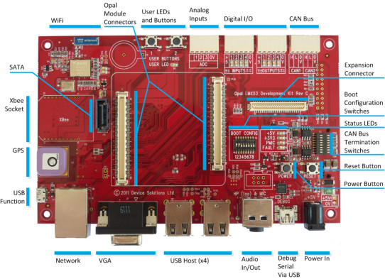
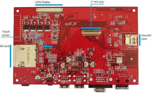
The diagrams below show the main components and connectors on the DB100 base-board.


Configuration Switches
The ODK includes two sets of configuration switches:
- Boot switches to configure which storage device is used at boot time.
- CAN termination switches
Boot Configuration
The i.MX53 can boot from many different sources. The ODK is setup to enable several of these, but not all possibilities. The most common options are shown below.
Refer to the documentation for your chosen Operating System to ensure your boot device is programmed correctly.
Boot from: | 1 | 2 | 3 | 4 | 5 | 6 | 7 | 8 |
|---|---|---|---|---|---|---|---|---|
SD Card | ON | ON | OFF | OFF | OFF | ON | OFF | OFF |
Micro SD | OFF | ON | OFF | OFF | OFF | ON | OFF | OFF |
Opal internal NAND | OFF | OFF | ON | OFF | OFF | OFF | ON | OFF |
USB | OFF | OFF | OFF | OFF | OFF | OFF | OFF | ON |
If you have a RevC board, the boot settings are:
Boot from: | 1 | 2 | 3 | 4 | 5 | 6 | 7 | 8 |
|---|---|---|---|---|---|---|---|---|
SD Card | ON | ON | OFF | OFF | OFF | OFF | OFF | OFF |
USB | OFF | OFF | OFF | OFF | OFF | OFF | OFF | ON |
CAN Termination
The ODK includes optional 60ohm termination resistors for each CAN channel. Turn the appropriate switch ON to enable the termination.
Switch | Terminates |
|---|---|
1 | CAN1_H |
2 | - |
3 | CAN1_L |
4 | - |
5 | CAN2_H |
6 | - |
7 | CAN2_L |
8 | - |
Opal i.MX53 CPU Module
While the Opal Development Kit is shown without the Opal module in several pictures in this manual, the board you receive includes a module that is already attached. Should you ever need to fit another module, ensure that the orientation is correct before powering up the board. The square corner should be next to the VGA connector. You can also use the silk screen outline as a guide.
Power and Status LEDs
The ODK includes the following power and status LEDs:
LED | Color | Description |
|---|---|---|
+5V | Green | Indicates there is power on the +5V rail |
+3V3 | Green | Indicates there is power on the main +3.3V rails |
PMIC | Green | Indicates the PMIC is operating correctly |
STBY | Red | Indicates the PMIC is in Standby or has a fault. |
Powering the board
The ODK should be powered with the supplied 5V adapter which connects to the barrel connector.
There are two variants of the DA9053 shipped on Opal modules. Some have the auto power-on features enabled and others do not.
For the boards with this feature disabled, the active LEDs will be the +5V LED and the STBY LED when power is applied to the board. Press the POWER button to fully power on the board so it boots.
The following table shows the normal state of the LEDs.
LED | After attaching +5V | After POWER button pressed |
|---|---|---|
+5V | ON | ON |
+3V3 | OFF | ON |
PMIC | OFF | ON |
STBY | ON | OFF |
The auto power-on boards will go straight to the "After POWER button pressed" state and will boot as soon as power is applied to the board.
Serial Debug and Configuration
Serial debug and configuration is necessary for most operating systems. The ODK configures UART4 from the i.MX53 for this purpose and provides an interface to it via USB using an on-board Serial-to-USB converter IC.
The IC is an FTDI FT232RQ or FT230XS device. Drivers are included in Windows 7, but if your PC does not recognize the device, driver can be downloaded from www.ftdichip.com.
The USB connection is enabled as soon as 5V is applied to the board, and your PC terminal can be connected at this point. You will need to re-connect your terminal application only if you remove power completely from the ODK.
Note for Revision D Hardware: The Rev D hardware has a problem with the debug port. The correct sequence to get this working is:
- Attach power to the Opal Development Kit
- Press the power button
- Connect the USB cable (or remove and re-insert if it is already connected)
- Open and connect your terminal application
The serial port will remain connected while there is power on the board. Pressing RESET is OK, but you will need to repeat the sequence if power is removed.
Software Development
Refer to the documentation for you chosen Operating System for details on how to develop applications for Opal.
Hardware Revisions
Revision | Changes |
|---|---|
C | Prototype version. |
D | Final Prototype release.
|
1.0 | First Release.
|
1.1 | Changes and bug fixes:
|