Topaz Design Guide
- Martin Welford
This section provides a check-list of everything you need to consider when designing with the Topaz CPU Module.
Click here to download the Topaz Development Kit schematic.
Free Design Review
We are here to help with your design!
Please email support@devicesolutions.net with your design questions. We also offer a free design review service before you commit to PCB layout.
Power Supply
For mains powered designs, we suggest that VIN is connected to 5V. This allows the same power supply to be used for powering USB devices if the host function is used in your design. Be sure to pull the PSU_LION signal low.
For battery powered applications, VIN can be connected to a LiIon battery. Pull the PSU_LION pin to VIN in this case.
Boot Mode
Topaz supports three main boot modes:
- Boot from NAND Flash – normal operation
- USB boot mode – used for firmware updates
- SD Card boot mode as an alternative to NAND flash boot
The i.MX25 supports many additional boot modes and determines the boot source by sampling several pins on startup. These pins are mostly the LCD signals and 10k pull-up or pull-down resistors can be used to set the appropriate value at boot time. This does not impact LCD performance.
For high-volume production the internal fuses can be set up to avoid having to fit pull-up/down resistors.
Signal | Boot Function | Setting (0=pull down, 1=pull up) |
|---|---|---|
BOOT_MODE[1] |
| Main boot setting. Use jumper to select:00 Boot from NAND or SD Card11 Boot from USB |
BOOT_MODE[0] |
|
|
LCD_VSYNC | BT_UART_SRC[2] | 0 |
LCD_HSYNC | BT_UART_SRC[1] | 0 |
LCD_D15 | BT_UART_SRC[0] | 0 |
LCD_D14 | BT_EEPROM_CFG | 1 |
LCD_D13 | BT_SRC[1] | 0 |
LCD_D12 | BT_SRC[0] | 0 |
LCD_D11 | MT_SPARE_SIZE | 0 |
LCD_D10 | MT_MLC_SEL | 0 |
LCD_D9 | BT_USB_SRC[1] | 0 |
LCD_D8 | BT_USB_SRC[0] | 0 Boot from NAND or eSDHC11 Boot from eSDHC2 |
LCD_D7 | BT_BUS_WIDTH[1] | 0 |
LCD_D6 | BT_BUS_WIDTH[0] | 0 |
LCD_D5 | BT_PAGE_SIZE[1] | NAND Page size [1:0]00 512 bytes01 2048 bytes 10 4096 bytes11 Reserved |
LCD_D4 | BT_PAGE_SIZE[0] |
|
LCD_D3 | BT_MEM_TYPE[1] | NAND address cycles [1:0]00 3 address cycles01 4 address cycles10 5 address cycles11 Reserved |
LCD_D2 | BT_MEM_TYPE[0] |
|
LCD_D1 | BT_MEM_CTL[1] | 0 NAND Boot1 SD Card Boot |
LCD_D0 | BT_MEM_CTL[0] | 1 |
PWM | BT_LPB_FREQ[2] | 0 |
LCD_OE_ACD | BT_LPB_FREQ[1] | 0 |
LCD_LSLK | BT_LPB_FREQ[0] | 0 |
Settings for NAND options fitted to Topaz:
Part / Manufacturer | Size | Page Size (bytes) | Address Cycles | BT_PAGE_SIZE[1:0] | BT_MEM_TYPE[1:0] | ||
|
|
|
| LD5 | LD4 | LD3 | LD2 |
NAND512R3A2CZA6E Numonyx/ST Micro | 512Mbit/64Mbyte | 512 | 4 | 0 | 0 | 0 | 1 |
NAND01GR3B2BZA6E Numonyx/ST Micro | 1GBit/128Mbyte | 2048 | 4 | 0 | 1 | 0 | 1 |
MT29F1G08ABCHMicron | 1GBit/128MByte | 2048 | 4 | 0 | 1 | 0 | 1 |
NAND02GR3B2DZA6E Numonyx/ST Micro | 2GBit/256MByte | 2048 | 5 | 0 | 1 | 1 | 0 |
Use the IOMux Tool
The i.MX25 relies on multiplexing to bring out all its various functions onto a relatively limited number of signal pins. Getting to grips with this in a design can be difficult, which is where the IOMux tool comes in useful. TO download the tool, go to the following address and search for "pin mux tool".
+http://www.freescale.com/webapp/sps/site/prod_summary.jsp?code=i.MX257&fpsp=1&tab=Design_Tools_Tab+
Once you have this downloaded and running, download and open the Topaz file from the Topaz product page on devicesolutions.net. This defines all the pins used on the Topaz CPU module, so you know that any free signals are available for you to use. The IOMux tool looks like this:
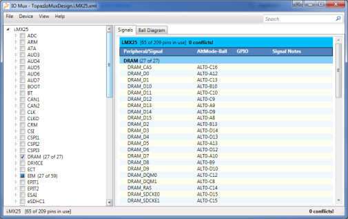
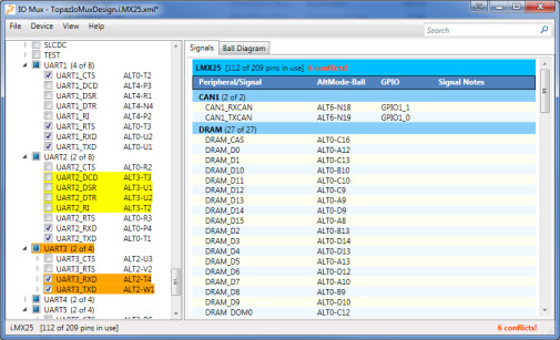
To use the tool, just select the features you need in your design. The tool will show pins in use as yellow, and conflicts as orange. With a bit of trial and error you should be able to come up with a combination that works for your product.
IOMux files are a great way to communicate exact requirements between everyone involved in your design.
Check all 1.8V signals
Make sure you have the latest schematic symbol and check every signal to make sure you know it operates at the voltage you expect.
I2C1 Signals
The I2C1 function signals must be used for I2C ONLY. They go to the PMIC on the module and will prevent the secondary 3V3 regulator from being enabled if connect to anything else. No pull-ups are required – these are on the module too.
The PMIC uses address 0x54. Any devices with conflicting addresses (including some EEPROMS) should use one of the other I2C busses.
Expose Debug Interfaces
All base-board designs should expose the following functions to allow programming and debug:
- USB OTG port. This should be setup as either a function port, or OTG port to enable software updates.
- Boot mode switches. Make sure you can switch between USB boot and NAND or SD card boot.
- Serial port. UART1 is the best option, but you can use another one if your boot software is configured for it.
- Ethernet. This is essential if you are doing Windows CE development!
Bring out unused pins to test points on prototypes
This is especially true if you are designing with the LGA version. A costly re-spin can result if you can't get at an important signal. Sometimes we can direct you to a point on the module to solder to; however almost all the I/O signals go directly from the i.MX25 BGA to the pads making it impossible to get to once the module is fitted to your base-board.
Production Programming
Programming Topaz firmware in production can be accomplished in a number of ways. The most universal way is to use the USB OTG port and the Topaz Flasher software provided by GuruCE (which works for all supported Operating Systems). Other options are available, but require customization work. Please contact us to discuss your requirements.
Ethernet MAC Addresses
Topaz modules do not include a MAC address. We can supply a small number from our block for prototypes, however you will need to purchase addresses for production quantities.
These can be purchased through IEEE. There are two options for doing so:
- IAB which gives you 4096 addresses: http://standards.ieee.org/develop/regauth/iab/
- OUI if you need more: http://standards.ieee.org/develop/regauth/oui/index.html