QDK System Components
- Martin Welford
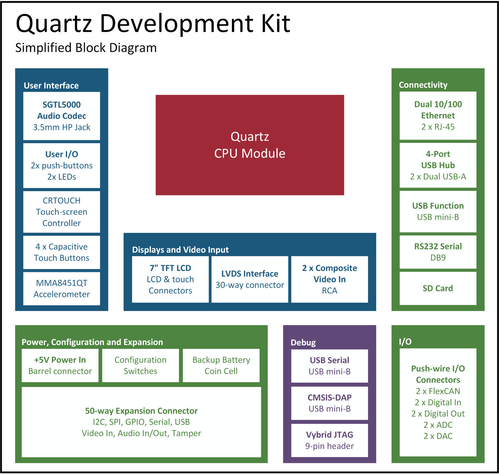
This page has details on each of the system components that make up the Quartz Development Kit.
The block diagram below shows the main components. Click the image to enlarge.
Quartz CPU Module
The Quartz CPU Module is at the core of the QDK. Quartz includes a Freescale Vybrid VF6xx processor with Cortex-A5 and Cortex-M4 ARM cores. There is also 256MBytes DDR3 RAM, 256MBytes NAND flash and dual 10/100 Ethernet PHYs. The module and dev kit connect using two 100-pin Hirose connectors.
The connectors on the QDK are Hirose FX11A-100P-SV0.5.
User Interface Components
Audio
Stereo audio output is provided on a 3.5mm jack connector. This is driven by a Freescale SGTL5000 codec. The microphone input, line input and line output signals from the codec are available on teh 51-way expansion connector.
User I/O
The QDK includes the following application accessible buttons and LEDs:
| Button/LED | GPIO Pin |
|---|---|
| BUTTON1 | PTD24 |
| BUTTON2 | PTD25 |
| LED1 (Green) | PTD29 |
| LED2 (Red) | PTD30 |
Touch Controller
A Freescale CRTOUCH chip is included on the QDK and provides resistive touch screen functionality as well as 4 capacitive touch buttons. It interfaces to the Vybrid chip via the I2C2 bus.
Accelerometer
The QDK includes a Freescale MMA8451Q accelerometer connected to the Vybrid via the I2C3 bus. INT1 from the accelerometer is connected to PTA23 on the Vybrid.
Display and Video Input
7" TFT LCD Interface
The QDK ships with an optional 800x480 7" Datavision DTFS070A5SHLA-D02 TFT display. This panel includes a 4-wire resistive touch screen that is also supported on the development kit.
LVDS Interface
A LVDS transmitter chip is included on the QDK and interfaces to a 30-way connector. This is identical to the connector on the Device Solutions Opal Development Kit and the i.MX53 Quick Start Board (QSB) and supports the Freescale 10.1" LVDS-1 display with capacitive touch. It can be purchased from Freescale here.
Composite Video In
The Vybrid processor includes 4 video inputs for composite signals. Two of these are available on RCA connectors and the remainign two can be accessed via the 51-way expansion connector.
Connectivity
Dual 10/100 Ethernet
The QDK has 2 RJ-45 network connectors providing 10/100 Ethernet functionality. These can be configured as independent ports or take advantage of the layer-2 switch present on the Vybrid processor. Consult the software documentation for your Operating System for details on how to configure this functionality.
USB Host
The QDK has 4 USB host ports. These operate at 480Mbps and this functionality is provided by an SMSC USB chip IC.
USB Function
The USB mini-B port next to the main power input is connected to one of the OTG ports on the Vybrid processor. This is configured as USB function-only mode and operates at 480Mbps.
RS232 Serial
A DB9 connector provides RS232 serial functionality on the Quartz Development Kit. This port is connected to SCI0 on the Vybrid processor and provides Tx, Rx, RTS and CTS signals.
SD Card
The QDK includes a standard SD card connector. This can be used as a boot source or data storage.
I/O Features
The QDK includes push-wire connector interfaces for digital and analog I/O along with FlexCAN.
These connectors are AVX 9276 series and accept 18-24AWG sold and stranded wires. To remove wires, insert the supplied tool into the slot above the wire and pull the wire out.
The QDK includes interface names printed next to each pin.
FlexCAN
The QDK includes FlexCAN transceivers on both channels. Optional 60-ohm termination is provided by the switches labelled CAN TERM to the left of the Quartz module. Turn these switches ON to enable the termination.
Digital Inputs
The Quartz Development Kit includes 2 digital inputs. These are protected from noise and spikes by a voltage divider, 5.6V zener diode and 100nF capacitor. Refer to the schematics for details in the input circuit. There are 2 LEDs on these ports to give a visual indication when the input is high.
| Input | GPIO Pin |
|---|---|
| INPUT 1 | PTB20 |
| INPUT 2 | PTB21 |
Digital Outputs
The 2 digital outputs on the QDK use p-Channel FETs with a +5V high-side configuration. Each output can supply up to 1A, but the total current will depend on the input power supply. There are LED indicators on each output showing when it is active.
| Output | GPIO Pin |
|---|---|
| OUTPUT 1 | PTB23 |
| OUTPUT 2 | PTB22 |
Analog to Digital Converters (ADC)
The ADC channels are connected directly through to the Vybrid processor and have NO INPUT PROTECTION. The maximum input voltage is 3.3V.
Be careful when connecting signals to the ADC inputs. Voltages outside the specification can cause permanent damage to the Vybrid processor.
| ADC Channel | Vybrid ADC Input |
|---|---|
| 0 | ADC0SE9 |
| 1 | ADC0SE8 |
Digital to Analog Converters (DAC)
The QDK provides 2 analog outputs on the push-wire connectors. They are connected directly to DAC outputs from the Vybrid processor. Like the ADC channels, there is no protection circuitry on these signals. The maximum output voltage from these pins is 3.3V.
| DAC Channel | Vybrid DAC Output |
|---|---|
| 0 | DACO0 |
| 1 | DACO1 |
Power, Configuration and Expansion
Input Power
The QDK requires a 5V input supply. This can be connected via the 2.1mm barrel connector or the 0.1" 2-pin header.
A 2A plug pack is supplied with the kit, however a larger supply may be required should you connect large loads to the digital outputs, or a display with a high current requirement.
Configuration and CAN Termination Switches
The Boot Configuration and CAN Termination switches are located to the left of the Quartz module. The first 4 switches control the boot source for the Vybrid processor. The options are: The QDK includes optional 60-ohm termination resistors for each CAN channel. Turn the switches on to enable the termination.Boot Configuration
Boot from: 0 1 2 3 SD Card ON ON ON OFF NAND Flash OFF ON OFF OFF USB OFF OFF ON OFF CAN Termination
Switch Terminates 5 CAN1_L 6 CAN1_H 7 CAN2_L 8 CAN2_H
Expansion Connector
There is a 51-way expansion connector on the QDK to provide access to signals not commonly used. Features available on this connector include:
- I2C (ports 1 and 3)
- UART (SCI3)
- Audio microphone input and stereo line in/out
- 2x Video input channels
- Port D signals used for QSPI
- USB Host port
| Signal | Pin | Pin | Signal |
|---|---|---|---|
| +5V | 1 | 2 | +3.3V |
| +5V | 3 | 4 | +3.3V |
| I2C1_SCL | 5 | 6 | PTD0 |
| I2C1_SDA | 7 | 8 | PTD1 |
| I2C3_SCL | 9 | 10 | PTD2 |
| I2C3_SDA | 11 | 12 | PTD3 |
| 0V | 13 | 14 | PTD4 |
| USB4_DP | 15 | 16 | PTD5 |
| USB4_DM | 17 | 18 | PTD6 |
| 0V | 19 | 20 | PTD7 |
| AUDIO_LINEIN_L | 21 | 22 | PTD8 |
| AUDIO_LINEIN_R | 23 | 24 | PTD9 |
| 0V | 25 | 26 | PTD10 |
| AUDIO_MIC | 27 | 28 | PTD11 |
| 0V | 29 | 30 | PTD12 |
| PTE20 | 31 | 32 | PTD13 |
| SCI3_TX | 33 | 34 | PTB2 |
| SCI3_RX | 35 | 36 | PTB1 |
| 0V | 37 | 38 | PTB0 |
| TAMPER0 | 39 | 40 | 0V |
| TAMPER1 | 41 | 42 | VADCSE2 |
| TAMPER2 | 43 | 44 | VADCSE3 |
| TAMPER3 | 45 | 46 | 0V |
| TAMPER4 | 47 | 48 | AUDIO_LINEOUT_L |
| TAMPER5 | 49 | 50 | AUDIO_LINEOUT_R |
| 0V | 51 |
Debug Interfaces
USB Serial
The primary serial output from the Quartz module can be found on the Serial Debug USB mini-B connector located at the bottom left hand corner of the QDK. See the Getting Started section for information on setting up the required driver on your PC.
CMSIS-DAP
The QDK includes a Kinetis K20 micro controller which provides CMSIS-DAP debug functionality. This interfaces to your PC via a USB mini-B connector and can be found next to the debug serial USB coonnector on the left-hand side of the board.
CMSIS-DAP is suported by the ARM DS-5 tools.
JTAG
A standard ARM 9-pin JTAG connector is located next to the configuration switches on the QDK.