Getting to know the Development Kit
These images show the location of the key features on the development kit (click for larger images).
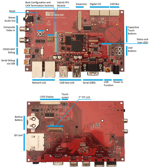
Configuration Switches
The Boot Configuration and CAN Termination switches are located to the left of the Quartz module.
Boot Configuration
The first 4 switches control the boot source for the Vybrid processor. The options are:
| Boot from: | 0 | 1 | 2 | 3 |
|---|---|---|---|---|
| SD Card | OFF | OFF | OFF | OFF |
| NAND Flash | OFF | OFF | OFF | OFF |
| USB | OFF | OFF | OFF | OFF |
CAN Termination
The QDK includes optional 60-ohm termination resistors for each CAN channel. Turn the switches on to enable the termination.
| Switch | Terminates |
|---|---|
| 5 | CAN1_L |
| 6 | CAN1_H |
| 7 | CAN2_L |
| 8 | CAN2_H |
Power and Status LEDs
The power and status LEDs are located on the right-hand side of the board, just under the capacitive touch buttons.
| LED | Color | Description |
|---|---|---|
| +5V | Red | Indicates there is power on main +5V input. |
| +3V3 | Red | Indicated the +3.3V power supply is operating correctly. |
| RESET | Orange | Indicates the board is in reset. The board can be reset from the push button, K20 micro controller or JTAG. |
| LED1 | Green | User accessible LED connected to PTD29. |
| LED2 | Green | User accessible LED connected to PTD30. |
Powering up the board
The Quartz Development Kit is supplied with a 5V/2A power pack. If you need to use an alternate supply, ensure that it meets the 5V/2A specification.
Serial Debug and Configuration
The QDK includes two options for serial debug.
| Connector | Port | Description |
|---|---|---|
| USB mini-B | SCI2 | Default output port for uBoot |
| DB9 | SCI0 | Secondary option |
The default serial output is on the Serial Debug USB mini-B port on the bottom left corner of the board.
This port is connected to SCI2 on the Vybrid processor and the USB interface is provided by an FTDI FT230XS IC. Drivers are included in Windows 7 and 8, but if your PC does not recognise the dervice, drivers can be downloaded from http://www.ftdichip.com/Drivers/VCP.htm.
The USB connection is enabled as soon as 5V is applied to the board, and your PC terminal can be connected at this point. You will need to re-connect your terminal application only if you removed the USB connection.
SCI0 from the Vybrid processor is connected to the K20 micro controller. We do not have access to the the combined CMSIS-DAP/serial application, but will update this documentation if this becomes available.
Software Debug Interfaces
The Quartz Development Kit includes several interfaces for debug of applications and low-level code.
| Interface | Description |
|---|---|
| CMSIS-DAP | The is available via the USB mini-B port on the left hand edge of the board labelled K20 Debug. It is the primary connection menthod for the ARM DS-5 tools. |
| JTAG | JTAG access to the Vybrid is provided via a standard ARM 9-pin connector located next to the boot switches. We have tested Segger J-Link + IAR Embedded Workbench and ARM RVI + DS-5 tools with this port. |
| Ethernet | Ethernet is an easy and fast option for download and debug of software when code is already running on your board. |
Software Application Development
Refer to the Getting Started Guide for your chosen Operating System.
We will add links when this documentation is available.
Hardware Revisions
| Revision | Changes |
|---|---|
| A | Initial prototype |